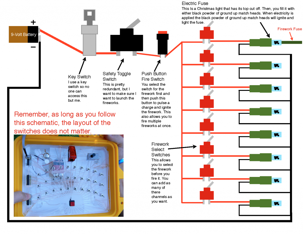
This is a wiring diagram of my Firework Detonator Box. A couple quick things that it doesn’t really explain is that, you can make any layout for the switches, as long as you wire it in this way. There is a connector in-between the lights and the box, so they can be taken of and the box closed. Finally, In the diagram I show 8 “channels,” you can put as many as you want. If you need a more detailed look, click here for the PDF. Seb I hope this helps you out and feel free to email me or leave a comment if you have any questions.

thanks for ur help hope u and ur family have a good xmas and new year
Any time and thank you, have a Merry Christmas to. If you have any more questions I am always available.
what are the black terminals on the side
Those are 10×2 pin connectors. One column is positive and the other is negative for the christmas lights. I put these is so I didn’t need to directly wire the lights to the box. To put the connectors in the wiring diagram above, simply put a break in between the red and black lines going to the lights. I hope that helps.
hi am stuck with the red wire running from push button to firework switches where it is split of and still on same wire how do it wire it up same for black
The wire coming from the push button switch can be attached to all the other switches because it is carrying the power to the individual power to the firework switches. The way I did it is, I took a section of copper and soldered the wire from the pushbutton switch on on side and then soldered all the the wires coming from the individual switches on the other side. You can do the same for the negative, but if you use the standard 10×2 pin connectors, you can simply run a wire down the side of all the pins on the negative side of the connector and solder it into place. I hope this helps, if you have any more questions, I have an email: lucas.weakley@gmail.com I think it will be more convenient if we talk that way.